
A directional control valve is the least glamorous component in a hydraulic circuit and the one that decides whether the machine feels precise or sloppy. Joystick problems in particular are almost never a valve problem — they are a linkage problem, and they get diagnosed as a valve problem because the lever is where the operator feels it.
This page covers the circuit-level decisions: spool centre condition, sections, flow rating, actuation method and how the valve matches the pump.
Centre condition: the first decision
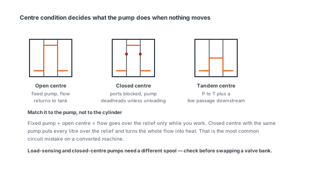
The spool’s centre position determines what the pump does when nothing is moving, and there are three common arrangements.
Open centre. With the spool centred, pump flow passes through the valve and back to tank at low pressure. Simple, cheap and tolerant, but it wastes the full pump flow whenever the operator is not working, which becomes heat.
Closed centre. With the spool centred, all ports are blocked. This suits a pressure-compensated variable pump, which destrokes to near-zero flow instead of dumping it over a relief valve. It is the right choice where the machine spends time holding pressure.
Tandem centre (float). The work ports are connected to each other and to tank, so an actuator can move freely. This is the position used for a float function on a loader or a dozer blade, where the implement follows the ground.
Choosing the wrong one produces a machine that either overheats at idle or cannot hold a load. The rule is straightforward: fixed-displacement pump with a relief valve means open centre; variable-displacement pressure-compensated pump means closed centre; free-floating implement means a float position on that section.
Sections and what they cost
Each section controls one function. A crane needs hoist, luff, slew and extension, plus outriggers — five or six sections. A compactor needs one or two.
Sections cost money, pressure drop and panel space, in that order of significance. Every section the oil passes through adds a pressure drop, and pressure drop multiplied by flow is heat. A six-section valve passing 60 L/min with a 10 bar drop per section is dissipating a kilowatt of heat in the valve body alone.
The design move that avoids this is to put high-flow functions on their own sections and to size each section for its own function rather than buying a valve rated for the largest flow and using it for everything.
Flow rating and the real constraint
Valve sections are rated for a nominal flow, but the number that matters is the pressure drop at that flow. Manufacturer curves show it and the difference between two valves of the same nominal rating can be a factor of two.
Practical guidance:
- Size the section for about 1.5 × the function’s actual flow. Going larger costs money and gives a mushy feel; going smaller produces heat and slow speed.
- Check simultaneous functions. If two functions move at once, the flow splits and each gets roughly half unless the valve is load-sensing with pressure compensation. A valve without compensation gives priority to the lightest load, which is why a crane slews instead of lifting when both levers are pulled.
- Watch the return line. Most undersized circuits are undersized on the return, not the pressure side. Return back pressure adds to every function’s load and shows up as heat and slow retraction.
Actuation: mechanical, pilot or electric
Direct mechanical. The lever moves the spool directly. Simple, no pilot supply, and limited to small valves and short lever travel. The feel is direct and the failure mode is visible — if the linkage is worn, the lever is sloppy and you can see it.
Hydraulic pilot. A small pilot valve sends oil to shift the main spool. This is how most multi-section mobile valves are arranged, because it allows a joystick to control several sections with low lever effort and allows remote mounting of the main valve bank.
Electro-proportional. A solenoid or proportional solenoid shifts the spool in proportion to an electrical signal. This is the choice when the machine has a controller, needs adjustable ramp rates, or needs the same valve controlled from two places — in the cab and at a remote pendant.
Cable remote. A mechanical cable between a lever and the valve. Cheap and common, and the source of most “the valve is worn” complaints. Cables stretch, bind and go out of adjustment.
Why joystick complaints are usually linkage
An operator reports “the joystick is vague”. The usual causes, in order of frequency:
- Worn pins and clevises in the linkage between lever and spool. A millimetre of slop at four joints is a centimetre of dead travel at the lever.
- Stretched or misadjusted cable on a cable-actuated valve.
- Spool not returning to centre, usually from a broken or weakened centring spring.
- Contamination causing spool stiction — the valve moves but not smoothly, and it feels worse when cold.
- Actual valve wear, which is last, not first.
The diagnostic is to disconnect the linkage and move the spool by hand. If the spool moves cleanly and the function responds, the valve is fine and the problem is upstream. This takes five minutes and prevents a lot of unnecessary valve replacement.
Load sensing versus fixed displacement
A load-sensing system adjusts pump flow and pressure to what the functions demand, so the system delivers only the flow being used at only the pressure the heaviest function needs. A fixed-displacement system delivers full flow at all times, and whatever is not used goes over the relief valve as heat.
The choice is economic. Load sensing costs more and saves fuel and heat on machines with widely varying duty. Fixed displacement is cheaper and entirely adequate on machines with one dominant function and predictable duty — a tail lift, a tipper, a compactor with a single ram.
The matching rule that is easy to get wrong: a load-sensing valve needs a load-sensing pump. Fitting a load-sensing valve to a fixed pump gives you the cost without the benefit, and it is a common retrofit mistake.
What to specify on a valve
- Centre condition for each section, not just the valve.
- Number of sections and the function on each, with the flow each one needs.
- Nominal flow and maximum pressure, plus the acceptable pressure drop.
- Actuation method — direct lever, hydraulic pilot with pilot pressure, or electro-proportional with voltage and signal type.
- Port threads and locations, which is where most installation problems start.
- Whether load sensing is present on both valve and pump.
- Relief valve setting on the inlet, and whether individual port reliefs are needed on any function.
Where this sits in a whole-machine enquiry
A directional valve is rarely the reason a customer asks for a cylinder, but it is often the reason a machine feels wrong. If you are specifying cylinders and power units together, send the number of functions, the flow and pressure for each, and whether they ever move at the same time. That is enough to say whether the circuit needs a load-sensing pump and a compensating valve, or whether a simple open-centre valve and a fixed pump will do the job for a third of the cost.