
Steel plant hydraulics is a materials problem wearing a mechanical disguise. The forces are high but not extraordinary; what is extraordinary is the environment the cylinder has to survive while delivering them.
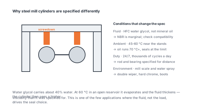
Three environments in one plant
A steel plant is not one environment. A ladle turret sees radiant heat from liquid steel at 1,600 °C but almost no dust. A descaling header sits in high-pressure water and mill scale. A run-out table or a transfer car sees neither heat nor water but a continuous rain of oxide flakes.
Each of those puts a different part of the cylinder under attack. Radiant heat attacks the seals and the hydraulic fluid. Scale attacks the rod and the wiper. Water attacks the rod plating and the cylinder exterior. A cylinder that is right for one position will be wrong for the other two, which is why mill cylinders are specified per position rather than per plant.
Fire-resistant fluid changes the design
Most steel plants run water-glycol (HFC) or anhydrous fluid near molten metal, because a mineral oil leak near a ladle is a fire risk that no plant accepts. ISO 12922 covers the fluid classes; what matters for the cylinder is what the fluid does to the materials.
Water-glycol is 35 to 45 percent water. It conducts, it corrodes carbon steel wherever the plating is breached, and it attacks some elastomers. Three consequences:
- Rod material. A hard-chrome plated carbon steel rod develops pinholes, and once water reaches the substrate the corrosion lifts the chrome from underneath. Stainless or nickel-chrome base material removes the mechanism.
- Seal material. NBR is marginal in water-glycol at temperature; FKM or EPDM is the usual choice, and the wiper material has to match.
- Cylinder internals. Unpainted carbon steel surfaces and untreated aluminium are both a problem. Internal surfaces need plating or a suitable coating, not just a coat of paint on the outside.
Heat is a distance problem
Radiant heat flux falls with the square of distance, so the cheapest thermal fix is mechanical: move the cylinder, or put something in the way. A stainless heat shield with a 20 mm air gap typically drops the seal temperature by 60 to 80 °C on a ladle application, which is the difference between NBR at its limit and FKM with margin.
Where a shield is not possible, the fluid becomes the limit. Mineral oil in a cylinder near a heat source degrades at about 10 °C above 60 °C for every additional 10 °C, so an application running 90 °C halves oil life roughly every 10 degrees above 60. Water-glycol tolerates more but evaporates water, and the concentration has to be checked monthly or the fire resistance quietly disappears.
Cylinder families that fit mill duty
Positioning and maintenance functions on a steel plant usually need long stroke at moderate force rather than short stroke at high force. The HSG family covers 430 to 3,500 mm of stroke at 20 MPa with bore and rod from 50/28 to 200/140 mm across 7 models, which suits run-out table gates, transfer car positioning and maintenance cranes.
Where a short, high-force push is needed in a relatively clean part of the plant, a scissor hoist geometry can be adapted: the HTT range covers 2.8 to 15.4 t with 3 to 6 inch bores, 10 to 30 inch strokes and body lengths from 30.8 to 69 inches.
Neither is a purpose-built mill cylinder. For ladle and furnace positions the honest answer is that a standard range is the starting point and the specification is customised for fluid, seals, rod material and shielding.
What to send for a mill application
Position in the plant, ambient and radiant temperature, fluid type and concentration, cycles per heat, and the space available for a shield. Those five answers decide the seal material, the rod material and whether a standard model can be adapted or a custom cylinder is the right call.