
Every hydraulic power unit has a reservoir, and most of them are sized by a rule of thumb that nobody can explain. The usual rule is three times pump flow for industrial units, one to two times for mobile. Neither of those numbers is about cooling, and the reason matters, because the failure they prevent is not the one people think.
What the reservoir actually does
Three jobs, in order of importance:
- Supply oil to the pump inlet without cavitation, at all attitudes and temperatures.
- Let entrained air separate out and let contamination settle, which requires the oil to sit still for a while.
- Reject heat through its walls, which it does badly.
Cooling is the job people design for and the one a tank performs worst. That is the central point of this article.
Where the heat comes from
Every watt that goes into the system and does not come out as useful mechanical work leaves as heat. A pump that is 88 % efficient, a relief valve passing flow, a long line with pressure drop and an actuator doing work — all of it ends up in the oil.
Take a power unit with an 11 kW motor. If the overall efficiency from the motor shaft to useful work is around 70 %, then:
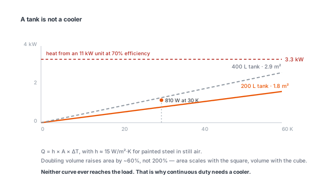
Heat = 11 × (1 − 0.70) = 3.3 kW
The hydraulic power calculator works this backwards from pressure and flow: it gives the hydraulic kW, the motor size at a stated efficiency, and the heat left over.
That is continuous while the unit is running. If it runs 60 % of the time, the average heat load is about 2 kW, but the peak is still 3.3 kW and the oil temperature responds to the average while the components see the peak.
How much a tank can reject
Heat leaves the tank by natural convection and radiation through the steel. The combined coefficient for a painted steel tank in still air is roughly 12 to 20 W/m²·K. Take 15.
Q = h × A × ΔT
If the oil sits at 60 °C in a 30 °C ambient, ΔT = 30 K. To reject 3.3 kW:
A = 3,300 / (15 × 30) = 7.3 m²
Now measure an actual tank. A 200-litre reservoir might be 1,000 × 500 × 400 mm. Total surface area is 2 × (0.5 + 0.4 + 0.2) = 2.2 m², and the bottom is usually against a frame or the floor and does not participate, so the effective area is nearer 1.8 m².
At 15 W/m²·K and 30 K, 1.8 m² rejects 15 × 1.8 × 30 = 810 W.
The tank can handle about a quarter of the heat load. Making it bigger does not close the gap: doubling the volume to 400 litres increases the surface area by roughly 60 %, not 300 %, because area scales with the square of linear dimension while volume scales with the cube. To reject 3.3 kW by natural convection alone you would need a tank the size of a room.
This is why continuous-running power units have coolers. The reservoir is not the cooling system and never was. Air-blast coolers reach effective coefficients of 50 to 100 W/m²·K on their fin area, which is why a cooler the size of a briefcase can do what a 400-litre tank cannot.
What the 3x rule is really for
Dwell time. Air entrained in the oil needs time to rise out, and the oil needs to be still for that to happen. Dwell time is simply:
t = V / Q
A 200-litre tank with a 40 L/min pump gives 5 minutes. The working figure usually quoted is three to five minutes of dwell for mineral oil, more if the oil is cold or foaming is already a problem.
Insufficient dwell time shows up as:
- Pump cavitation and noise, because aerated oil is compressible.
- Spongey actuators, for the same reason.
- Rapid oil oxidation, because air is the oxidiser and warm, agitated, aerated oil oxidises fastest.
- Foam overflowing the breather, which people misdiagnose as overfilling.
A tank that is too small for the flow fails on air release long before it fails on temperature. This is what the 3× rule protects against, and it is why the rule is stated against pump flow rather than against power.
Mobile units are the exception, and they prove the rule
A DC power unit on a truck has a 20 to 40-litre tank serving a pump that may run at 6 to 10 L/min. Dwell time is 3 to 5 minutes, which is fine. The heat load, however, would be fatal if the unit ran continuously — and it does not.
A liftgate or a tipping body runs for 20 to 40 seconds and then sits for minutes. Average heat load over an hour is a small fraction of the peak, and the oil has time to cool between cycles. The tank is small because the duty cycle is intermittent, not because the sizing rule was ignored.
Put the same unit on a continuous duty — a compactor cycling every 30 seconds, a conveyor take-up holding pressure all day — and a 30-litre tank will overheat within an hour. The unit has not changed; the duty has.
Any power unit specified for intermittent service needs the duty cycle written into the enquiry. “Continuous,” “intermittent” and “10 % duty” are three different machines.
Temperature: what you are actually protecting
Mineral oil oxidises roughly twice as fast for every 10 °C rise above 60 °C. This is the usual rule of thumb, and it is why 60 °C is the practical ceiling for continuous operation even though the oil will physically work at 90 °C.
The other limits are component limits:
- Seals: nitrile is comfortable to about 100 °C, but life falls rapidly above 80 °C. Polyurethane is worse; it hydrolyses in hot oil with water in it.
- Oil viscosity: at 80 °C an ISO VG 46 oil is thin enough to drop below the minimum film thickness in many pumps.
- Clearances: aluminium and steel expand at different rates. A valve body and its spool at 90 °C are not the same fit as at 40 °C.
Design for a steady-state oil temperature of 45 to 55 °C in the hottest ambient you expect, not 60 °C in a temperate one.
Details worth specifying
Most of these cost nothing at design stage and cannot be added later:
- A baffle between return and suction, forcing the oil to travel the length of the tank. Without it, fresh hot return oil goes straight back into the pump.
- Return line ending below the minimum oil level, to stop the returning stream from whipping air in.
- Suction strainer located 50 to 100 mm off the bottom, so it draws from settled oil and not from the sediment layer.
- A breather with a filter, sized for the full volume swing of the cylinders. A breather that cannot pass the air will either pressurise or vacuum the tank.
- A drain plug at the lowest point and a cleaning hatch. Tanks that cannot be cleaned do not get cleaned.
The sizing check, in order
- Dwell time: V / Q ≥ 3 minutes. This sets the minimum volume.
- Volume swing: tank must hold the extended cylinder volume plus a static reserve above the suction at all times. A single 100-litre cylinder on a 60-litre tank is a tank that will run dry.
- Heat balance: compute the heat load, subtract what the tank walls reject, and size a cooler for the remainder.
- Attitude: if the machine tilts, the suction must stay covered at the maximum slope in every direction.
If you only do one of these, do the first one — and then be honest about the duty cycle, because it is the input that decides whether steps one and three give you the same answer.